Post Solar Build
Scan to join — no app, no login. You present the slides; questions pop as live polls.
Join at
…
Room code
····
0 joined
Introduction
Quality Assurance and Quality Control (QAQC)
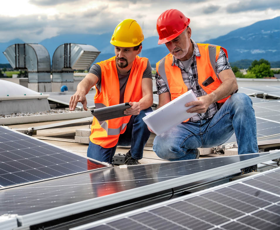
After the construction is completed, a quality check – called Quality Assurance and Quality Control (or QAQC) – is performed.
QAQC involves a detailed checklist of procedures that verify all components function correctly, the installation meets contractual and warranty specifications, and the work is completed within defined quality and performance parameters.
This leads to a ‘punch list’, a document which lists all pending tasks for rectification. Once these tasks are completed and the punch list closed out, the solar system can be commissioned.
The QAQC verifies the quality of the installation, ensures that the system is free from defects, and conforms to all stated customer requirements. This step is crucial in preventing costly issues later.
What does the "A" in QAQC stand for?
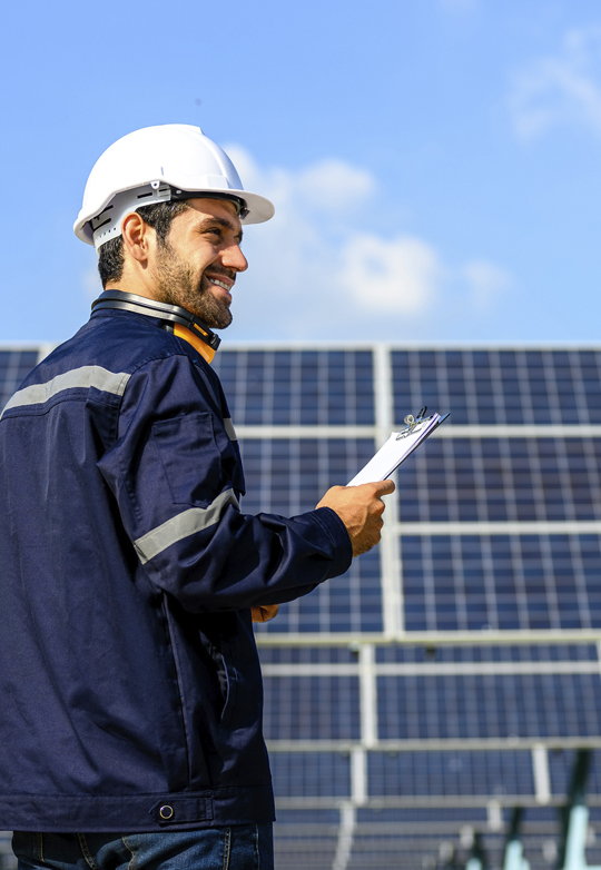
Quality Assurance and Quality Control – Systems Inspector
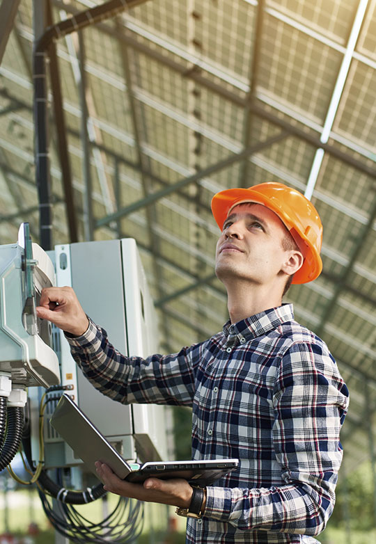
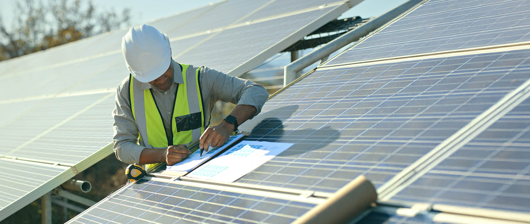
Once construction is completed, a qualified photovoltaic (or PV) systems inspector should assess the installation quality of the project. All system components should be inspected for defects at this time.
If deficiencies are identified during this quality check, contractors are required to rectify these issues. Final payment is only made after all deficiencies have been addressed.
The QAQC check ensures that, after construction and before commissioning, the system has been properly installed and thoroughly inspected, and is operational according to quality and customer standards.
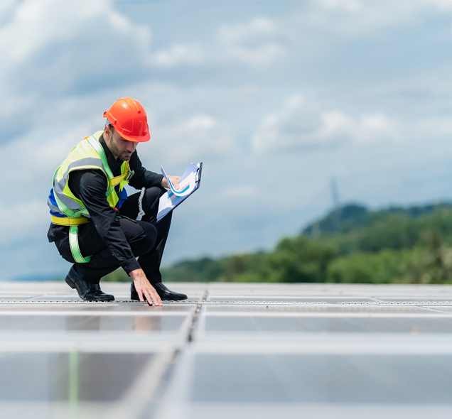
Quality Assurance and Quality Control – CEC
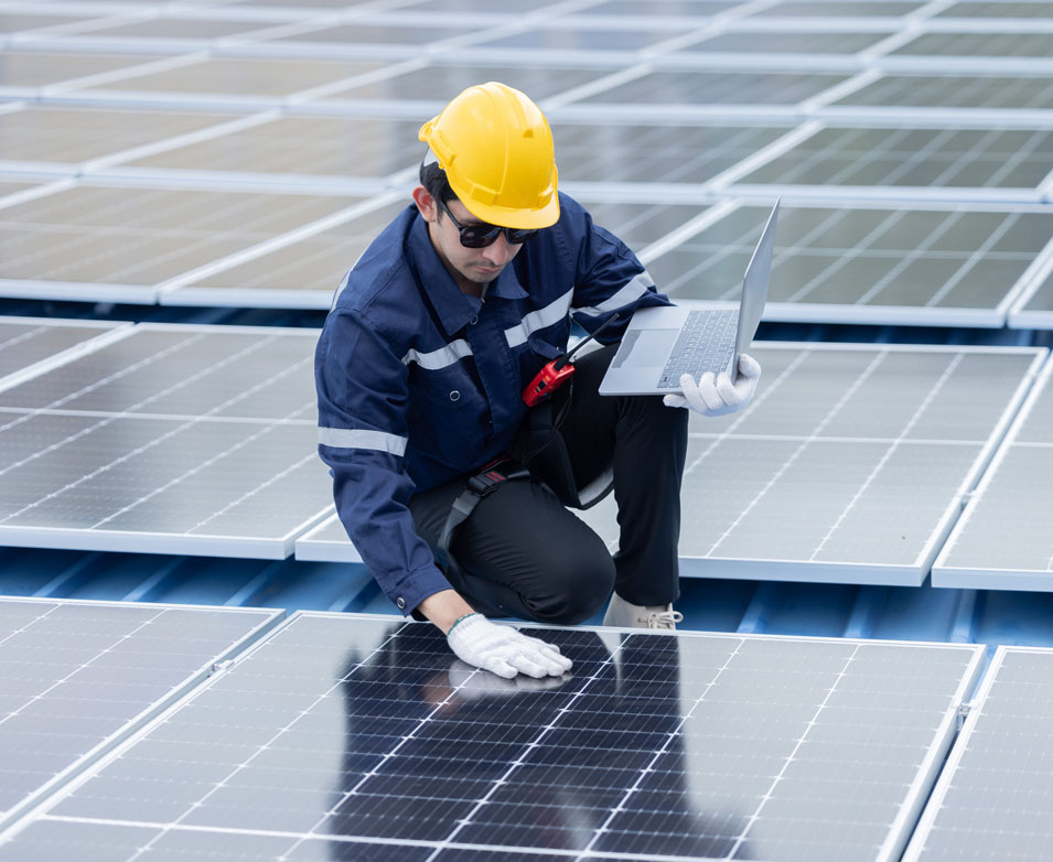
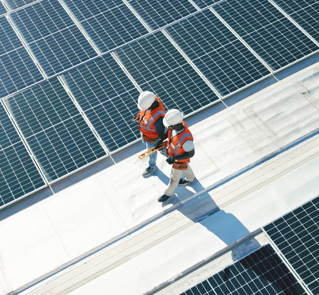
Community Energy Champions (CEC) or Energy Team members are qualified to conduct regular visual post-construction inspections, which significantly contribute to the early detection of potential issues. They visually inspect systems after installation and periodically throughout their lifespan to confirm their good condition. These are visual quality control checks. Electrical components should not be touched for safety reasons.
Visual inspection of wiring for faults.
Make sure that the wires are all connected properly and check for any wiring faults. Check for nicks in the protective coating around the wiring and the cables, and for damaged wiring. Ensure that the leads on the back of the module are tucked up neatly underneath the racking and the module, and are not hanging down onto the roof.
Visual check of solar modules’ condition for damage and cleanliness.
Check for damaged or broken modules. See that they are not cracked, for instance. If a module is cracked, there will be a white mark where the glass is broken. Also make sure that the glass of the modules is clean – there might be dust, bird waste or snow on them.
Visual check to see if wires are being pinched too tightly by wire ties/zip ties.
Wires can be damaged if they are being pinched too tightly by wire ties or zip ties. No wires should be hanging onto the roof. They should all be neatly zip tied. Installers should use ultraviolet-resistant zip ties. This is because the ties are going to be in the sun all the time and the plastic should not break down.
Visual check for any damage to the PV equipment.
Check for general damage to the PV equipment – the modules, racking and inverters. Check if there has been any tampering with the conduits or the wires.
Visual check for any roof damage.
Along with the solar asset, it is important to protect the roof asset. Inspect the shingles to see that they are not lifted up or ripped. Check if any metal pieces are bent. In addition, check that there is a protective layer of rubber – called a sacrificial layer – underneath the blocks to protect the roof.
The Community Energy Champion is qualified to perform a portion of the QAQC
Examples of improper installation
Examples of improper installation – 1
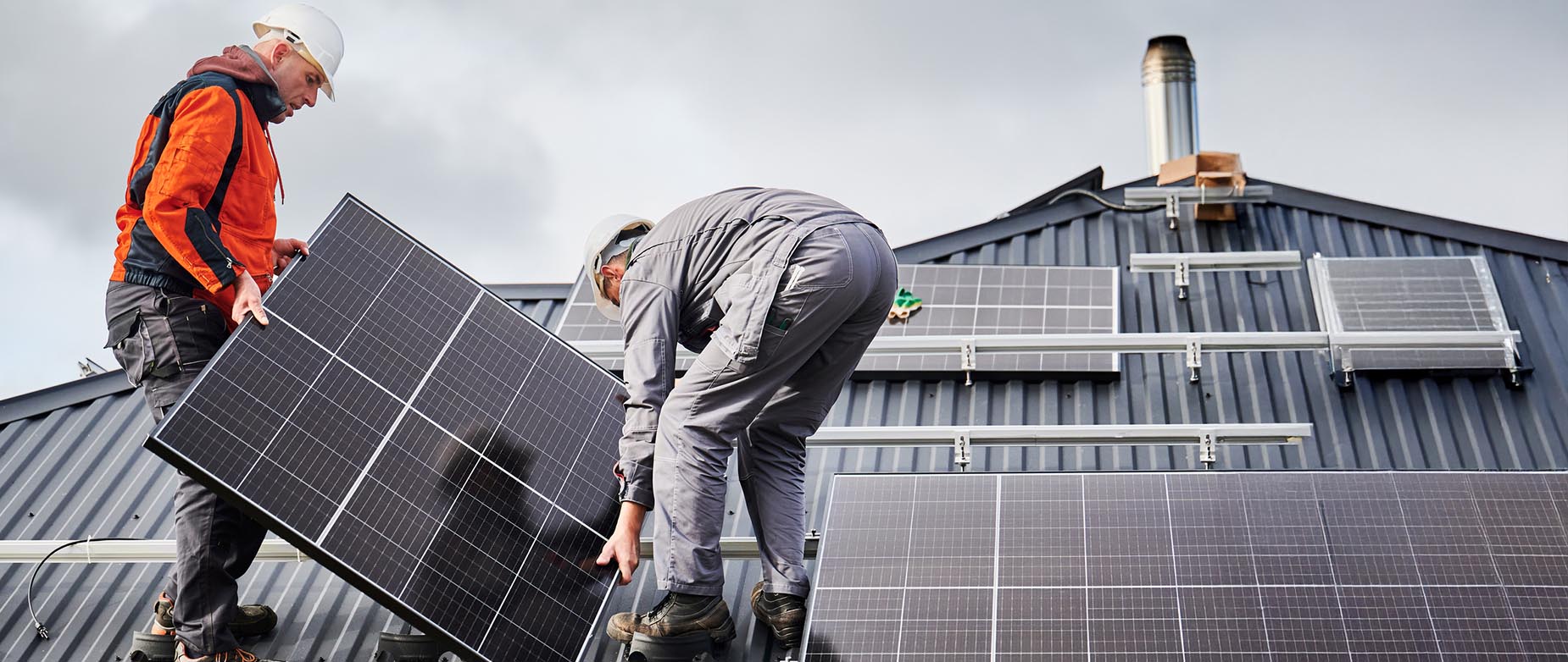
Inspections of newly installed solar powered systems are critical in preventing hazardous circumstances. Visually check the system after the installation, identify problem areas, and have somebody come in and fix them as soon as possible.
Let’s look at some examples of improper installation.
Examples of improper installation – 2
Defective connections.
The photo shows connectors running from one module to another connector in another module. Connectors should be closed and sealed properly. If any connectors are left open overnight, make sure that they are capped properly. No dew, rain or snow should get inside them.
The connectors in the photo have been clipped improperly. If any dirt or water gets in them, an ‘arc fault’ could be created, since electricity is running through those wires. An arc fault may be caused when an electrical current jumps between two conductive surfaces, creating a brief but powerful surge of heat and/or light. This could even lead to a fire.
There are tools to make sure that the connections are secure and that they have been closed and sealed properly.
Examples of improper installation – 3
Poorly installed wiring.
This photo shows poorly installed wires – the wires are coming out of the conduit and are not properly protected. The wires have to be inside the conduits. The wire dangling off the side of the roof is coming off the conduit and hitting the racking. The racking has sharp edges. So if a wire is hitting the racking and wearing against it, it will ultimately damage the wire’s protective film.
Examples of improper installation – 4
Fire hazard.
This photo shows a fire hazard. This generally does not happen, but nevertheless is a potential hazard to be aware of. Fires can be caused by faulty wiring, overheating or electrical flaws.
This can be avoided by: firstly, making sure that the equipment is of good quality and has no design flaws; and secondly, making sure that it has been installed and inspected properly.
Examples of improper installation – 5
Loose clamping.
After the racking and rails have been installed, the module is put on top of the rails and clamped down using the little piece of metal shown in the photo.
This, however, is a loose clamp. It is supposed to be on top of the module, holding it down to the racking, turned about 90 degrees. The bolt on the clamp has probably not been torqued enough or correctly. As a result, the clamp has slipped over time and loosened.
Punch lists review
Why are punch lists important after solar module installation?
QAQC review
What is the full form of QAQC? Why is it important?
QAQC Tests to perform

QAQC tests to perform – 1
Professional engineers can also be hired to perform QAQC
on the system. They will be able to do more in-depth checks.
Some of these tests are listed here.
QAQC tests to perform – 2
Test voltage and amperage of the strings of modules.
Engineers will test the voltage and amperage of the modules’ strings using a multimeter. This is to see if that is in line with what it should be, based on the design specifications. The gadget you see in the photo is a multimeter. It is hooked up to the string of modules via the connectors to measure the voltage and amperage.
The readings on the multimeter are compared with the design specifications. This will let testers calculate if the design of the electrical system is as it should be.
QAQC tests to perform – 3
Check grounding.
Engineers will also check for grounding and fault detection. One way this is done is by tracing the green grounding wire, seen in most systems, and making sure that it is grounded.
Grounding is critical for safety. It reduces the risk of electric shocks. Additionally, it also protects the solar equipment, and the building itself, from potential harm if there are lightning strikes.
QAQC tests to perform – 4
Check anti-islanding.
Another test is for anti-islanding. This is a requirement by
Hydro 1.
A situation where, if the grid goes down but the solar system stays live and is producing power, is called ‘islanding’. The solar system has, essentially, become an ‘island of power’ that is independent from the grid. Anti-islanding is, therefore, a safety feature in the inverter – when the grid goes down, the inverter also shuts down and will not produce any power.
QAQC tests to perform – 5
Perform a torque test on the modules’ clamps.
Torque tests are done on the clamps to ensure that the torque has been done to the rated specifications, as specified in the installation manual.
The tool that you see in the photo is a torque wrench. It is used to test how many pounds per square inch (or PSI) have been put on bolts. The installation manual specifies the torque, which all the clamps have to be torqued to, for all the racking.
QAQC tests to perform – 6
Perform a solar thermal test.
Thermal tests can be performed with infrared cameras. You can see in this photo that there are some cells showing up bright, like hot spots in the module. This means that they are hotter than the other cells.
The solar energy is getting concentrated in one or two cells and is not finding the busbars to travel throughout the module. It is trapped in those cells. This makes the temperature of these cells higher than the other surrounding cells and they show up as hot spots. Generally, all cells should be the same temperature.
This shows clearly that there is something wrong with those solar cells and that part of the solar module.
QAQC – Punch list
‘Punch lists’ are created after all checks and testing has been completed. It is a report that lists all the deficiencies that contractors need to correct and fix. Such reports are a standard practise in construction projects.
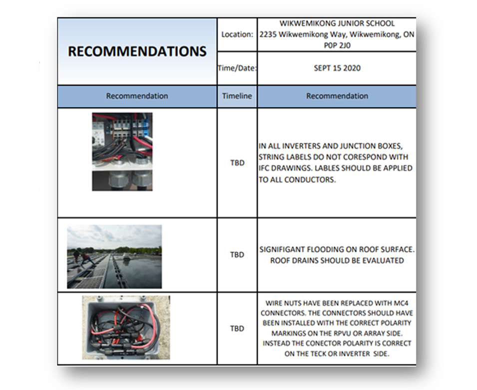
QAQC Recommendations are issued from Inspectors
Troubleshooting systems
Troubleshooting is a methodical process for identifying and fixing problems, by systematically eliminating points of failure within the system. If the solar system is not working as it should, conduct a step-by-step check of the different components installed. At each step, check if it might be the source of the problem and eliminate it if it is not. Then move on to the next point, and so on, till the fault is identified.
For example: You could first check the solar module. If that is not the problem, you would eliminate it from your list and then check the inverter. If the inverters too are not the source of the problem, you would then look at the combiner boxes or disconnects.
Troubleshooting systems – 1: Solar modules
When troubleshooting solar modules, you would pick up problems when doing voltage checks. It could also be that, while monitoring inverter readings, you see that the energy production is not what it should be – even though it is a sunny day – and then you know something's wrong.
Note that you should not touch the electrical components. Hire professionals to do this part of the work.
What are the troubleshooting steps for solar modules?
Use multimeters to check the modules.
The first thing to do is to test the solar modules themselves to see that they are functioning properly. A multimeter is used for this. The positive and negative multimeter leads are placed on the positive and negative MC4 connector wire at the end of the solar module. Before testing in this way, learn how to safely and comfortably use a multimeter.
Check the modules’ voltage and amperage values.
Check the voltage and amperage values from the module. The manufacturer’s specifications for the modules describe the open circuit voltage and the short circuit current value that the module should be producing. If the voltage and amperage values are significantly lower than the rated values on the label of the module, then the module is under-producing.
Check for physical damage.
Check the wires to be sure they are secure and not damaged in any way. Make sure that the modules are secure. Check that they are not physically damaged, for example, that there are no cracks in the glass.
This part of the QAQC testing
Troubleshooting systems – 2: Inverters
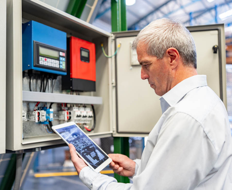
The next step in the troubleshooting process is to check the inverters. If monitoring has been set up in the system, it can be visualized on the phone or laptop. The first step would be to see if the inverter is on. If not, then turn the inverter on and off with the disconnect.
Let’s see the troubleshooting steps for inverters.
Identify the error log code number.
Next to the Inverter’s screen (See photo below ) are red, yellow and green lights, denoting not good, minor issue and good, respectively. If there is a red or yellow light, the screen will display an error code number.
Check the meaning of the code number
Use the inverter manufacturer’s O&M manual to reference that code and determine what it means. The O&M manual comes with the inverter.
Use the O&M manual’s error code troubleshooting steps to attempt to fix the issue.
The O&M manual also provides steps, based on the error code, on how to troubleshoot and fix that issue. Use the manual’s troubleshooting steps and attempt to fix the problem.
Contact the manufacturer's customer support team to resolve the issue.
If the above steps do not work, then contact the manufacturer’s customer support team.
Check for loose connections.
Sometimes, the issue may be as simple as a loose connection. So, check for those. The photo below shows a situation where some screws were not tightened correctly and the wire started to fall out. The burn marks show that that the wiring wasn’t properly done in the first place and created an arc fault.
Troubleshooting an inverter involves
Troubleshooting systems – 3: Combiner boxes/disconnects
If the fault in the system has still not been detected, then the combiner boxes and disconnect switches have to be checked.
Note that disconnects or combiners are at the alternating current (or AC) side of the system. You are not supposed to open up this type of equipment. A professional, licensed electrician should be with you to do this work. There is a risk of electrocution if you are not careful.
Let’s look at the troubleshooting steps for inverters.
Confirm that all wiring connections are tight.
A loose connection could cause fluctuating voltage or current output to the inverter. Make sure that all the connections are tight. When electricians open up the box, look for torque marks. Make sure they tighten the bolt and they put a flash through it. As the system gets older, sometimes the bolts loosen and then some flashes of the line don't match up. The system then needs to be torqued again to the proper tightness.
Validate all fuses in the box.
When checking the system, validate all fuses in the box. Check that they have correct resistance and continuity. The fuses that you see on a module board are often the same as in a combiner box. A red fuse means that it has tripped because something went wrong. Check for this in the fuses.
Make your calculations.
Measure and calculate incoming current and voltage from the arrays and validate the combined current and voltage output to the inverter. The electrician will do these calculations.
Measuring current will help determine if a cell has malfunctioned.
Measuring current on individual arrays or combining current measurements will help determine if a cell has malfunctioned. Use a multimeter to check all the electrical readings.
Grounding in electrical systems review
Why is grounding important in electrical systems?
Solar thermal test review
During a solar thermal test, what do 'hot spots' indicate?
Warranties – 1: Manufacturer's warranty
If troubleshooting has not worked, then you have to contact the customer support line for the manufacturer. Hopefully the equipment is still under warranty; you can then use your manufacturer's warranty.
A manufacturer’s warranty is a written guarantee to the buyer of a product. Its terms assure the replacement or repair of the product, if necessary, within a specified period after the purchase.
If you are claiming the warranty, a Return Merchandise Authorization (or RMA) process is initiated. The manufacturer will send a new piece of equipment and then you ship the old, broken piece of equipment back. The new equipment is then installed.
Note that it is very important to store all warranty documentation securely – whether in a database or in a binder. If you have to claim a warranty for any equipment, you need its serial number. You should be able to easily track and access the serial numbers of all the manufacturers’ warranties for all the equipment that you have.
Warranties – 2: Workmanship warranty
A workmanship warranty is offered to you by your installers. It provides the system owner with coverage against workmanship or installation errors.
Warranties – 3: Production guarantee

Solar modules also come with a production guarantee which assures a minimum initial energy production and a maximum annual production degradation.
Warranties – 4: Typical warranty periods

Different pieces of equipment have different time periods as their warranty. A typical warranty is based on the expected life span of the equipment.
Warranties are the same length of time as the expected lifespan of equipment
Solar monitoring – 1
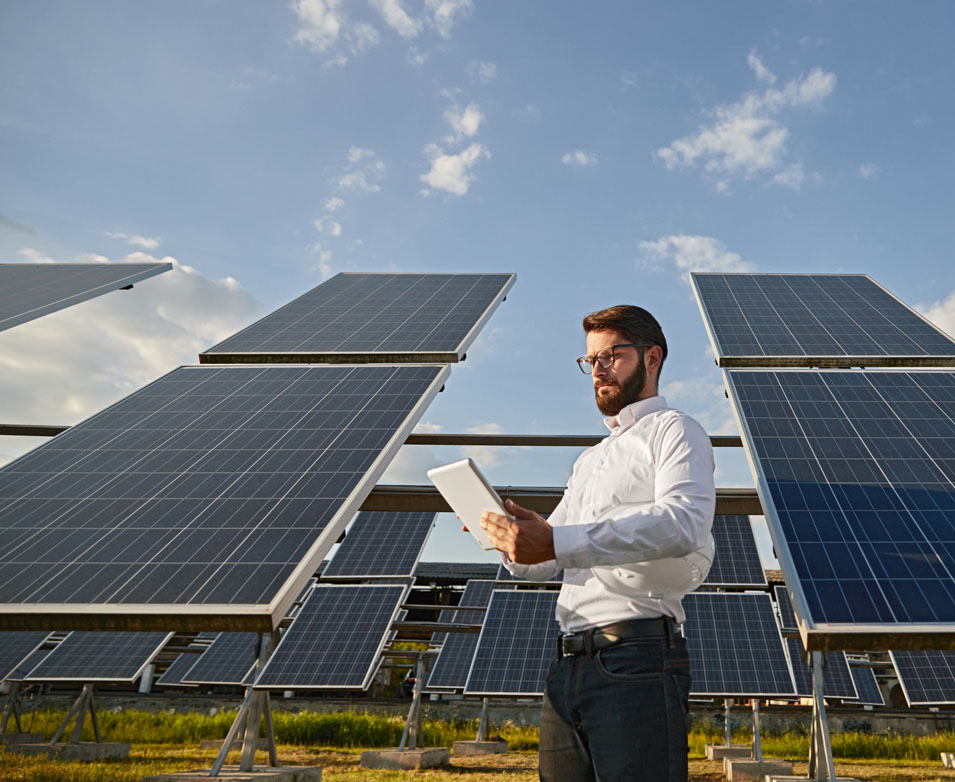
What is solar monitoring? Solar monitoring is extremely important. It comes into play after the system is fully installed and is operating as it should be. Operations and maintenance is important at this stage. And that involves a lot of monitoring.
After systems are commissioned, inverters are connected to online platforms (through the internet) which track the production of the solar array. Inverters transmit signals imbedded within the electrical signal. This is how they communicate to a platform. All inverters come with their own online monitoring platform, which you can sign up for.
You may need to run an internet cable from the inverter to a spot where a modem can be plugged in. You could also connect to the internet source, such as Wi-Fi, within the building. You could also use SIM cards or data cards. However, SIM cards might be more expensive in the long run, though, because you would have to pay a monthly fee for that data.
If the system is not working the combiner box should be checked for
Solar monitoring – 2
Monitoring platforms help monitor the system remotely. You don’t have to physically go to the system every time to check it. You can supervise system performance and production in real-time.You can set alerts on your phone, email or computers and receive notifications in case of any system malfunction.
Solar monitoring ensures that by tracking the system’s performance, you can confirm whether or not the modules are operating at peak efficiency. If needed, you can take steps to rectify the problem quickly, thus avoiding costly repairs later if the problem is left unattended.
A warranty can be delivered by
Solar monitoring – 3
It is important to constantly monitor and analyze the solar output of the system.
Solar monitoring makes it easy to track not only the performance of the system but its energy consumption versus production as well. This allows for maximizing the system’s efficiency.
By monitoring energy consumption along with the systems’ performance, solar monitoring enables building owners or homeowners to anticipate the fluctuations in their utility bills. They can thus understand the impact on their utility bills, calculate if they are getting the proper credit from Hydro 1, and track their savings.
Constant oversight of the system also alerts system owners to when maintenance or issues may arise. This leads to quickly identifying and fixing problems. Immediate notifications also mean that, by acting promptly, you can avoid costly repairs at a later stage and save money.
Why is it Important to Monitor Solar Output?
Solar monitoring
Types of system monitoring – 1
In solar monitoring, there are different kinds of systems to monitor.
Let us discuss them in detail.
Types of system monitoring – 2: String inverters (part 1)
String inverters
After the system is installed, it has to be commissioned. This is a simple process – you have to input some basic information, such as location, system size, and grid information. Usually the inverters have an LED display screen, or sometimes there is an app that you can sign into, which you can do on the phone. There is a step by-step process. An installation person could also help you on how to do the commissioning.
Then the inverter has to be connected to the internet. There are three ways of doing that.
• Connect it with an Ethernet cable, such as an RJ45 cable. You may need to run an internet cable from the inverter to a spot where a modem can be plugged in.
• Connect it with Wi-Fi. In this case, the inverter has to have a communications card. So when an inverter that is going to use Wi-Fi has been ordered, make sure that it has a communications card in it.
• You could also use SIM cards or data cards. This may work out to be expensive in the long run, though, because you would have to pay a monthly fee for that data.
Types of system monitoring – 3: String inverters (part 2)
String inverters [continued]
The inverter then transmits the solar array’s production information, through the internet, to the customer’s homepage.
The next step is to register your system with company’s website. The inverter is now able to communicate to the online monitoring platform. That is the platform that you would then log in to. You would then log into your computer to monitor the system remotely. You don’t have to physically go to the system every time to check it.
You can now get real-time information on the system’s production.
Note that you can only monitor the solar array as a whole, not individually.
Types of system monitoring – 4: Micro inverters (part 1)
Micro inverters
Microinverters are little boxes that are mounted to the racking itself, up on the rooftop, and they are fastened underneath the modules. Each individual module or sometimes two modules have their own microinverter. Leads connect them to the module. All microinverters have serial numbers associated with them. They also have QR codes that must be scanned. As the microinverters are installed, it is very important to start mapping, on the online monitoring platform, where all of the individual inverters are.
The system is mapped to show how each module is performing. This gives you access to monitor them online. It will show you which solar modules are connected to which specific microinverter. Details are available on how the module is performing not just on a string level but on an individual module level.
Types of system monitoring – 5: Micro inverters (part 2)
Micro inverters [continued]
We have seen that it is important to map micro inverters on the monitoring platform. This way, the location of each one of them can be pinpointed exactly on the platform. Each inverter has a unique bar code sticker, these have to be scanned and input into the platform in the correct sequence of their installation.
Mapping each inverter location enables individual monitoring. Let’s illustrate this with an example. Say there are 20 micro inverters mounted underneath the modules. If one of them malfunctions, it obviously has to be replaced. There is, however, no way of knowing which one of the 20 it is unless it has been correctly mapped on the platform. The problem can then be swiftly remedied.
Types of system monitoring – 6: Micro inverters (part 3)
Micro inverters [continued]
The relevant information is downloaded to the host. The data is transformed into real-time information on how the system is performing. You can then physically see on the monitoring platform how the modules are laid out and how they are performing.
Did you notice in the photo that the two or three modules on the last row, at bottom right, are a little bit darker? This alerts you immediately to the fact that these modules are not performing as well as the rest of the system. They may, for instance, be having some shading issues.
The monitoring platform will also have the numbers for how many kilowatts or watts each module is producing, maybe some weather information, and other details (see numbers in white at the top of the photo).
Types of system monitoring – 7: Power optimizers (part 1)
Power optimizers
Power optimizers are similar in concept to micro inverters – in that they are little boxes that get mounted onto the rails and they’re typically mounted behind the modules. You either have one for every module or one for two modules.
The major difference is that they output direct current (or DC) – they don't actually invert the power from DC to AC. They are DC to DC power boosters. They are, as the name suggests, optimizing output!
They have Maximum Power Point Tracking (or MPPT) functionality, so they optimize the power output. Basically, they get the most watts out of the sunlight hitting the modules as best as possible. This is achieved by varying the voltage in the MPPT curve.
Power optimizers have superior efficiency – nearly 99.5% peak efficiency. They come with a 25-year warranty. They have anti-islanding functionality as well, which is a crucial safety feature of solar energy systems.
Types of system monitoring – 8: Power optimizers (part 2)
Power optimizers [continued]
The performance of power optimizers can also be monitored and measured in real-time. They can be mapped on a monitoring platform, and can be easily accessed from a computer, smartphone or tablet.
Data presentation is available at the module, string and system levels. Automatic alerts are sent regarding system issues. The platform also enables visualization of PV production, building consumption, and self-consumption patterns.
String Inverter monitoring shows every individual panel performance
Document control review
Why do you need to store all paperwork safely?
Solar monitoring review
Why is solar monitoring an important part of a post-solar build?
Conclusion
Before concluding, let's quickly recap this lesson.
This training lesson emphasized QAQC checking and troubleshooting during the post-solar build phase of solar energy system installation. The QAQC check ensures the system is properly installed, thoroughly inspected, and operational according to quality and customer standards before commissioning. Community Energy Champions or Energy Team members perform visual post-construction checks. Improper installations are documented in a punch list, which is given to professional contractors or installers for rectification. After commissioning, system performance is monitored using online monitoring platforms, supporting operation and maintenance throughout the system's lifespan. Effective monitoring can significantly reduce downtime and enhance overall system efficiency.
In summary, post-installation involves conducting QAQC checks, fixing defects, commissioning the system, and ongoing monitoring and maintenance.
Thank you.