Quick pre-check
A quick baseline of what you already know — no grade, no pressure. Totally optional, and you can skip it.
💾 Sign in first so your results save to the dashboard.
Introduction
Electricity fundamentals—1: Photovoltaic power
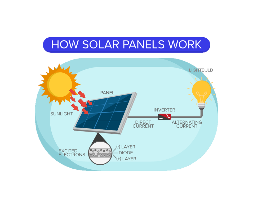
Let’s look at how do solar modules work. Solar energy is generated through photovoltaic power, or PV, for short. PV gets its name from the process of converting light (photons) to electricity (voltage), and this is called the ‘PV effect’. Photons are the smallest particles of light and electromagnetic energy.
The PV effect starts when sunlight (made of photons) strikes the surface of the solar module (made up of solar cells crafted from silicon). A solar module is layered, somewhat like a wafer. The top layer of cells is the negative layer and the bottom is the positive layer, and the two are separated by a diode in the middle. As the photons hit the negative layer, they are absorbed by the solar cells. This causes the electrons in the cells to travel in a circuit around and to the back of the module, and get reabsorbed into the positive layer. This keeps happening over and over again in a big circuit.
This creates Direct Current (or DC for short). This current goes into an inverter which converts it to Alternating Current (or AC for short), which is what is used in buildings and homes.
Where does the term "photovoltaic" come from?
Electricity fundamentals—2: What is electricity?
Electricity is the flow of electrons through a circuit, made up of a conductive material such as metal. The electrons flow from a source (battery or grid) along a conductor (or a wire) and produce current along a circuit.
The circuit must be closed for the electrons to flow. As you can see in the diagram, the battery is pushing the electrons through the circuit. When you place a resistor, say a light bulb, in that circuit, the electricity flowing through the wire will light up the bulb. Switches are installed into the circuit to interrupt the flow of current and shut the power off.
There are two types of current. In DC power, the electrons flow steadily in one direction. In AC power, they oscillate back and forth from positive to negative voltage, multiple times per seconds.
In Alternating Current, the standard frequency is 60 hertz, meaning the current changes direction 60 times /per second, while other regions may use different frequencies, such as 50 hertz.
AC voltage…
Electricity fundamentals – 3: Components of electricity
There are three components to electricity that are important to know:
Voltage. Unit: Volts (V)
Voltage is the electrical potential difference between two points in a circuit, which drives the movement of charged electrons (current) through a conductor. It determines how much energy each electron carries as it moves through the circuit.
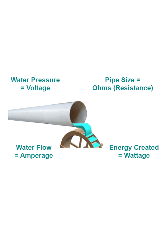
You can think of electricity as water going through a pipe, the water could be trickling through or gushing through the pipe. This pressure is called voltage, and its unit is volts (V). Higher voltages cause more electricity to flow through cables. Voltage is impacted by the distance it has to travel and also by temperature.
Amperage. Unit: Amps (A)
Amperes (or amps) measure the rate of electron flow in a complete electrical circuit, representing the amount of electric charge passing a point per second. It quantifies the actual current flowing through a system, while a system’s rated amperage indicates the maximum current it can safely handle without overheating or damage.
Continuing with the pipe analogy, the water pressure is also impacted by the size of the pipe it is flowing through. A large pipe will allow more water to flow through than a smaller one. So amperage—which is also known as current—is the flow of electricity, or the rate at which the electrons are moving, that is impacted by the size of the cable. It is represented by the symbol ‘I’ and its unit is ampere (A), often shortened to amp. For example, the big Hydro line cables will have more amperage than a laptop or mobile phone cord.
Wattage. Unit: Watts (W)
Wattage is the rate at which energy is transferred or consumed in an electrical system, such as lighting a bulb or powering a motor. It is measured in watts (W) and is also referred to as electrical power, represented by the symbol P in formulas.
Keeping to the pipe analogy, the flow and pressure will create some energy when the water comes out of the pipe. This energy is called wattage, and its unit is watt (W). Watts can be calculated by multiplying voltage (in volts) by current (in amperes).
What is voltage?
Electricity fundamentals – 4: Ohm’s Law
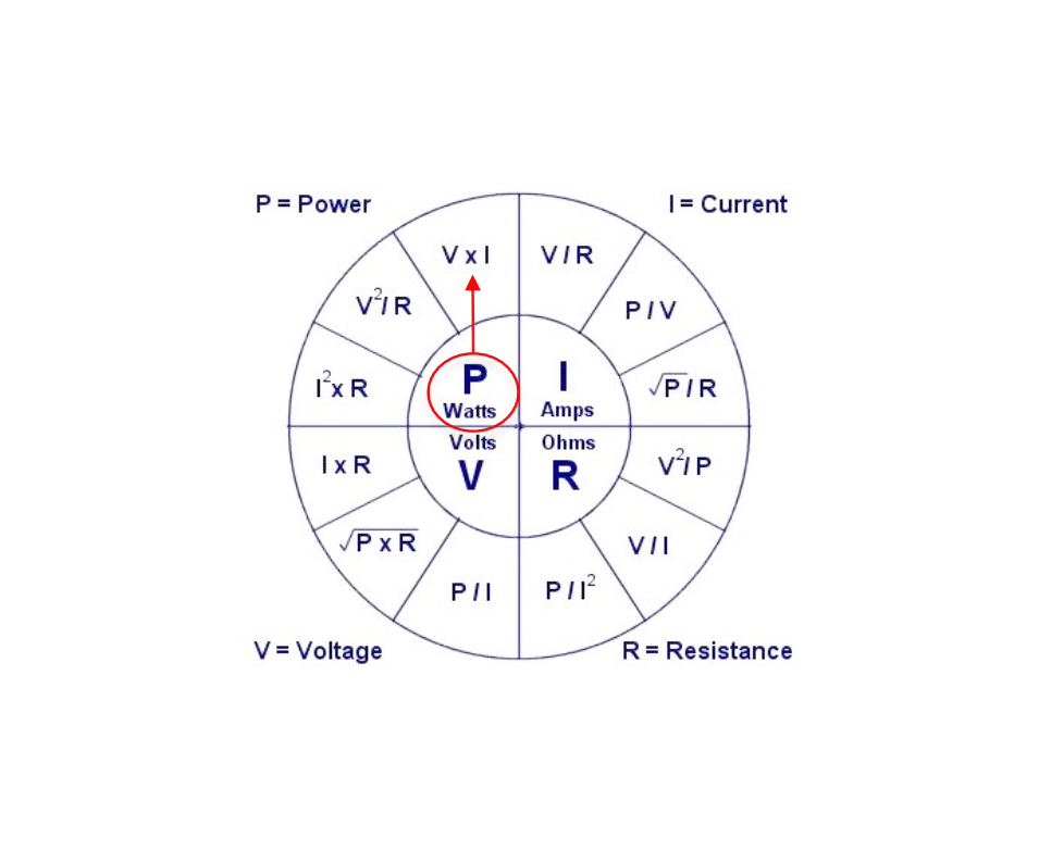
Ohm’s Law is a mathematical formula used to calculate the relationship between voltage, current, and resistance in an electrical circuit. The formula states:
V = I x R
In other words: V (voltage, measured in volts) is equal to current (represented by the symbol I, measured in amps) multiplied by resistance (represented by the symbol R, measured in ohms).
Relationship between the four
components of electricity
If a circuit is 120 volts and 480 watts, what is the current (amps)?
Solar module current generation review
<b>True or False?</b> Solar modules create Direct Current, this current goes into an inverter which converts it to Alternating Current.
Solar modules: Components – 1
The terms 'Solar module' and 'Solar panels' are often used interchangeably. Several solar cells—generally 60 or 72—strung together make up a solar module. Several solar modules strung together are called an array.
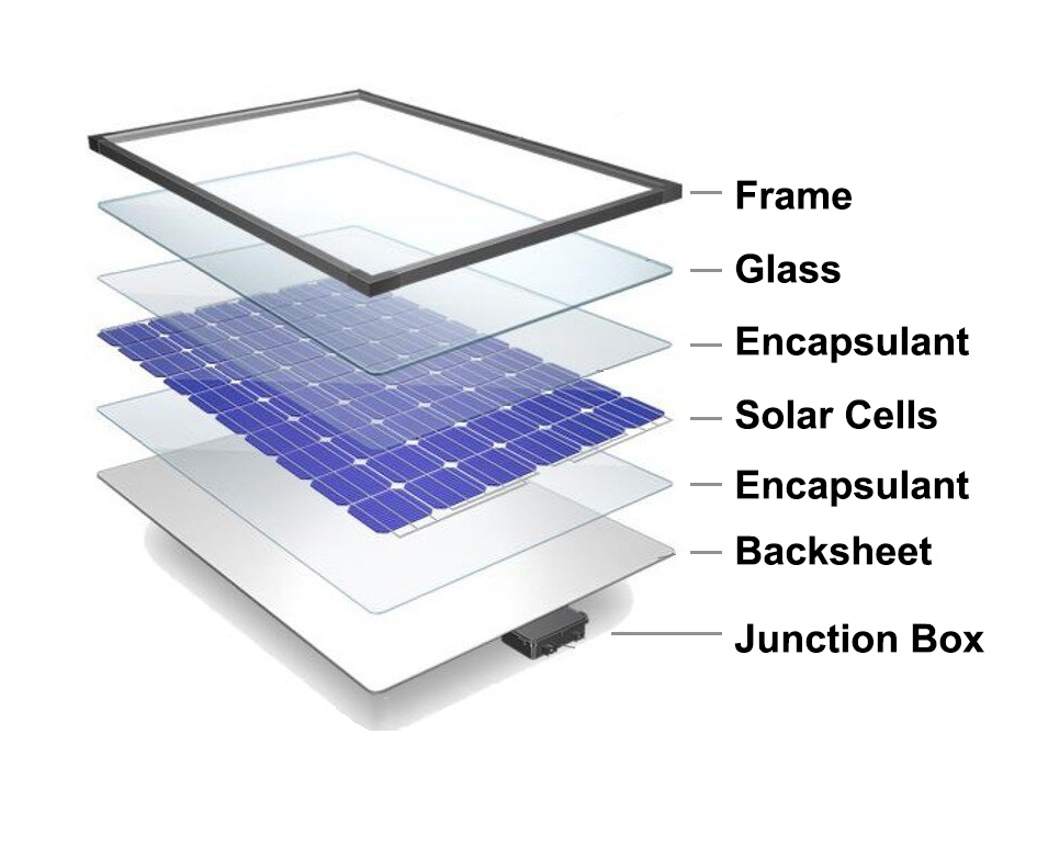
Solar modules are made of a few different components. They are assembled much like a sandwich. The top layer is anti-reflective glass, so that it does not create glare off the solar modules. It is not smooth; it is slightly textured to capture more sunlight into the cells. The glass makes it easy to clean and also protects the solar cells from dust, moisture or bird waste.
Then there is a layer of encapsulant, followed by a layer of solar cells, followed by another layer of encapsulant. Encapsulation is the process of sealing solar cells and other components with polymeric materials to ensure their longevity and effectiveness.
The bottom layer is a white backsheet. An aluminum frame protects all these components. The last piece of component is a junction box, placed at the bottom of the solar module.
Solar modules: Components – 2
Here you can see a blow-up of a corner of a solar module. Solar cells are welded very carefully together with an encapsulant and backsheet in the manufacturing process. Very thin pieces of aluminum are soldered to the cells very delicately. These are called busbars, which create pathways for the electrons to travel to the metal strip at the top. The cells within a module are wired in series, which means the voltage is additive. Energy then travels to the cross-connectors, into the wires at the back and out of the solar module to wherever it has to go.
In the solar world, when we talk of energy, we mean the wattage, or the peak power of a solar module. The output of each cell is about 0.5 volts. So a 60-cell module can produce about 30 volts.
System components: Solar modules
Solar modules activate with sunlight, converting it into electricity through the photovoltaic effect. The modules produce direct current (DC power). So installing the modules on the roof is the 'DC' part of the installation.
In our homes and businesses, we use alternating current (AC) power. However, many energy sources, such as solar modules and batteries, produce DC power, which must be converted to AC to be compatible with household outlets. This conversion is done by inverters, which are essential for transforming DC into AC so that electronic devices like computers, televisions, and phones can safely operate. AC is generally installed by an electrician. The Electrical Safety Authority's approval is needed for that installation as well.
AC power is generally more dangerous than DC because it can interfere with the heart and cause stronger muscle contractions, making it harder to let go if shocked. Since household electricity runs on 120V or 230V AC, it's important to be cautious around outlets and wiring. That said, high-voltage DC can also be dangerous, especially because it can create persistent electrical arcs. While both types of electricity can be hazardous at high enough levels, AC is the bigger concern in everyday home and workplace settings—so always handle electrical devices with care!
Solar panels produce…
System components: Solar panels
Solar cells are made of silicon. Silicon is a semiconductor and creates the photovoltaic effect. The solar cells are treated with things like phosphorus and boron to make the positive and negative layers.
There are three different kinds of solar modules. Nowadays there is a fourth type as well, which is discussed here.
- Bifacial modules
- Monocrystalline modules
- Polycrystalline modules
- Thin film modules
Note: When choosing which solar modules to purchase for a solar project, you have to:
(a) consider the budget; and
(b) the efficiencies that are needed.
Bifacial
They are about 22–23% efficient. A bifacial is a photovoltaic solar cell that can produce electrical energy when illuminated on either of its surfaces, front or rear. It can capture sunlight from both the front and back surfaces.
Monocrystalline
Monocrystalline modules are preferred for rooftop installations (as are polycrystalline). Monocrystalline modules have about 18–23% efficiency. You can recognize if a solar module is mono by the shape of the solar cells—the corners are always cut at an angle. A monocrystalline module looks like it has small white diamonds between the solar cells. Monocrystalline is a single silicon crystal that was grown in a laboratory and then thinly sliced into wafers. Since there is more control over the environment the crystalline is growing in, they are more efficient.
Polycrystalline
Polycrystalline modules are preferred for rooftop installations (as are monocrystalline). Polycrystalline modules have about 17–21% efficiency, lower than monocrystalline. They are, however, more cost-effective than mono. You can recognize if a solar module is polycrystalline by the shape of the solar cells—the corners are always straight. A module will always have square-shaped solar cells. Poly is crystalline mined out of the ground, melted down, cut into crystals, and thinly sliced.
Thin film
A thin film module is a massive sheet of flexible and very delicate crystalline. It is rarely used in Canada unless there's a very specific need for it. Such modules are 8–14% efficient, the least among the different kinds of solar modules. This is because it can get easily damaged (for example, due to hail or wind) or get twisted the wrong way. Cracks which you cannot see—called micro-cracks—then develop and efficiency drops. However, since thin film can be rolled and unrolled like a spool, it is useful if you need to deploy solar power quickly.
What do "monocrystalline" and "polycrystalline" refer to?
Top layer of a solar module review
Why is the top layer of solar modules made of slightly textured glass?
AC or DC power review
<b>What kind of power do solar modules produce: DC or AC?</b>
Solar module efficiency: Increasing efficiencies
The efficiency of solar modules has increased significantly over the years. In the 1950s, solar modules were very expensive and only about 6% efficient, producing 20 watts. In 2012, efficiency increased to 15% producing 200 watts. By 2018, efficiency had increased to 18.7%, producing 320 watts. Since the efficiency of solar modules of the same size has been steadily increasing, we now have higher efficiencies. By 2023, modules had upwards of 23% efficiency. More efficient modules mean more power produced per unit area.
Two solar panels are the exact same physical size, but one produces 400 W and the other 350 W. Which is more efficient?
Solar module efficiency: Peak sun hours – 1
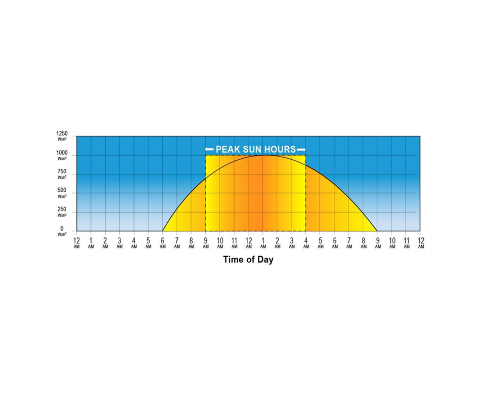
One way to measure the efficiency of a module is by calculating 'peak sun hours', which is the unit of measure for power delivered from the sun.
One peak sun hour is 1000 watts per meter square. You get peak sun hours in the middle of the day when the sun is shining most strongly, for instance, between 10 am and 2–3 pm. The graph shows the time of day and the irradiance hitting the solar modules. The bell curve shows the natural curve of sunlight over the day. When the sun is directly overhead, the angle of sunlight hitting the solar modules is very steep, almost perpendicular. This is why we have maximum power around noon.
Note that peak sun hours are determined also by geographical location (the sun is closer to the equator so it will be more intense) and time of year (summer produces more sun in the northern hemisphere).
Peak sun hours…
Solar module efficiency: Peak sun hours – 2
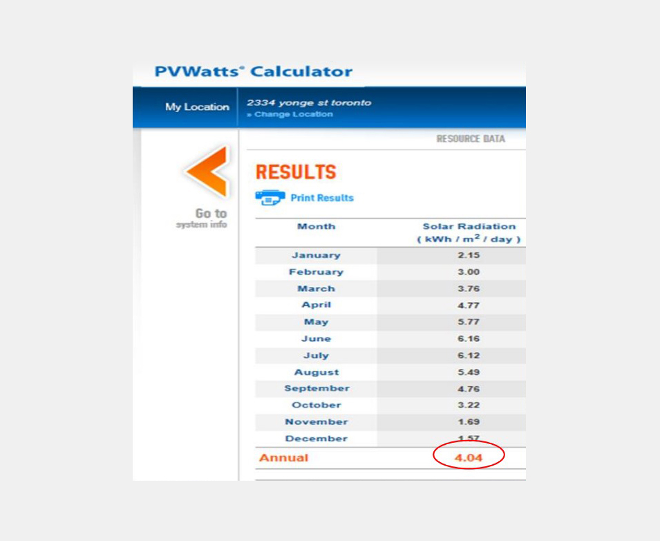
The amount of peak sun hours can be easily calculated for each month, as shown in this photo. This location has 2.15 peak sun hours a day in January, 3 hours in February, 3.76 hours in March, and so on for the whole year. The average number of peak sun hours per day for this location is 4.04 hours.
This data is useful when planning solar system installations.
How much sun does this site get? What is the system going to produce?
These are important questions to take into consideration.
There is software that can generate the relevant data. It combines weather data with sunlight hours and irradiance and tracks that history over time to see what the peak sunlight hours would be for a particular location.
Benefits of higher efficiency solar panels
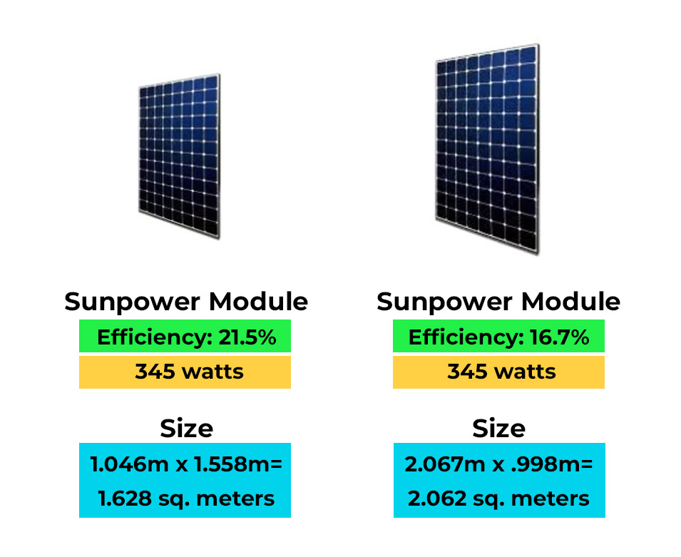
Higher efficiency means more watts delivered from a smaller per unit area.
The module on the left is about 1.6 meter square in size and is generating 345 watts; it is 21.5% efficient. The module on the right is about 2 square meters and is also generating 345 watts; it is 16.7% efficient.
Both modules are generating the same amount of power but their efficiencies are different. So how do you choose between them?
The crucial difference is in the size of the modules. The module on the left is more efficient because it is producing more energy per unit area.
Solar panels degrade from…
Solar module characteristics
Now we come to the wiring of solar modules. The positive and negative wires are called 'whips'. Whips can be connected either in series or in parallel. Only after the wiring is done will power (DC power) start flowing through the modules and connectors to the inverter, which then will convert it into AC power.
Wiring modules in series
Modules wired in series are called 'Strings'. The positive lead of one module is connected to the negative lead of the next module. The circuit runs through each module and gains voltage every time it runs through the module. For example, if the modules had 50 volts each, this would increase from 50 to 100 to 250 volts, and so on, until it reaches the end of the string. Wiring the modules in series increases the voltage of that string.
Wiring modules in parallel
When modules are wired in parallel, the positive lead of one module is connected to the positive lead of the next module, and so on. Wiring the modules in parallel increases the amperage of that string.
Bypass diodes
All cells must work together to keep the current flowing. The module is only as good as the weakest cell within that string. Let’s say a leaf landed on one of the solar cells (where it says ‘shade’ at the bottom of the photo) and is blocking one of the cells. That solar cell can no longer produce power. It does the exact opposite—it turns into a resistor and doesn't allow any electricity to go through it. The current will run up to the shaded solar cell and, because it can’t get past this area—it will get stuck.
Bypass diodes help prevent power loss by allowing current to flow around shaded or damaged sections of a solar module. When a section experiences higher resistance, the diodes activate, creating an alternate path for the current within the junction box and bypassing the affected area. In this case, the current would bypass the first two series altogether through the first diode (at the top left in the photo). It would start from the top of the third series and continue through the circuit.
As a result, about one-third of power is lost because the current skipped over the first two series of solar cells. However, the advantage is that rather than the entire circuit not working because of one small shaded area, the module can still generate two-thirds of the power it would otherwise have generated.
If there were no bypass diodes, the current would be stuck at the shaded area and no power would be generated. If the current is forced through an unproductive cell, it could burn out the cell entirely.
The junction box on a solar panel contains…
Solar module warranty – 1
At the procurement stage of the project, it's important to consider the solar module warranty when choosing the equipment for the project.
One is a Component Warranty for the product. It can be claimed that the frame is falling off or the lamination process wasn't done properly, or the back sheet is starting to mould due to faulty manufacturing processes.
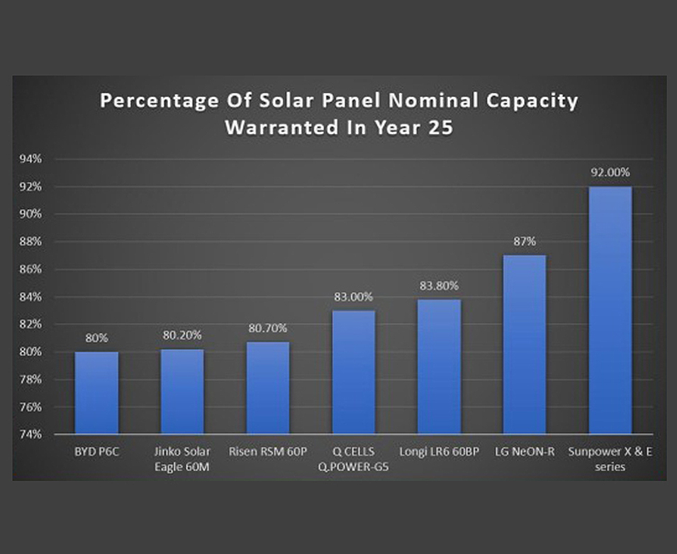
The other is a Performance (or production) Warranty. When exposed to sunlight, solar cells naturally degrade in their ability to produce power over time. This is called ‘light-induced degradation’. Generally, you lose about 0.5% production per year. This means that, over the course of 25 years, the module’s performance will decrease to about 80% of the power that it used to produce at the start of its life.
Manufacturers acknowledge the loss in solar modules' performance and write it in the model specifications. Most warranty their product for 25 years. That means that the module will produce 80% in Year 25 as compared with Year 1. So, at the end of 25 years, the modules may need to be replaced because they might be at the end of their usable life span.
Here are some comparisons of module percentages and what their warranty is at the end of Year 25. Different module manufacturers provide different percentages and different structures to their production warranties.
Solar module warranty – 2
An important consideration when looking at a performance warranty is also being able to gauge whether the solar manufacturer is going to be around in 25 years or not.
This means looking at the bankability of the manufacturer as well. If the company is not around in Year 15 when you want to claim the warranty, then you cannot have a replacement or your warranty value back. Consider the manufacturer’s history, such as: Is the company’s technology durable and reliable? Is it in other businesses? Is it building solar projects too? Does it comply with regulations? How is it regarded in the industry?
Solar module specification label – 1
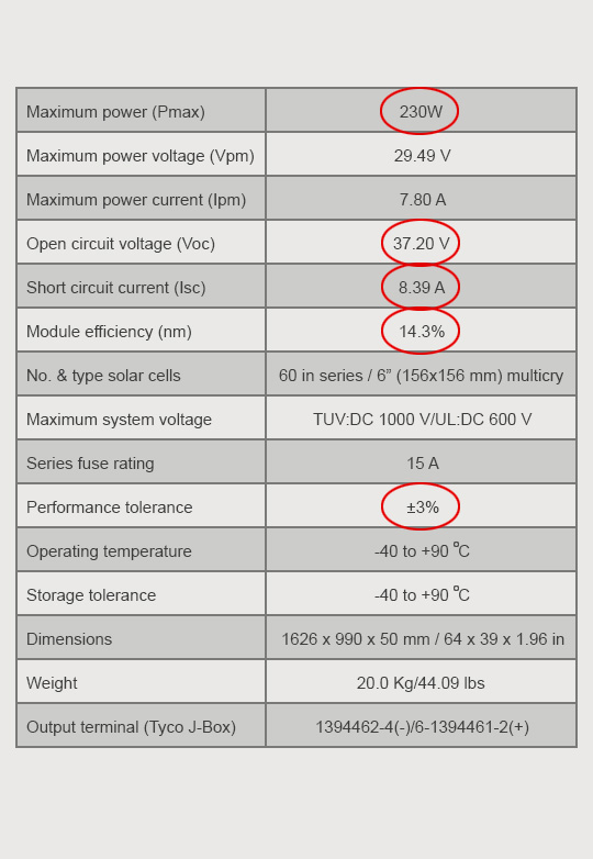
Here is an example of the specification label on a solar module. All solar modules have this datasheet. It provides general information about the solar module that has been purchased.
Maximum power
This is the maximum wattage, or peak power, that this module can produce. So, peak sunlight hours are going to produce a maximum of 230 watts.
Open circuit voltage
This is the maximum voltage this module can produce under standard testing conditions.
Short circuit current
This is the maximum amps this module can produce.
Module efficiency
This denotes how much of the sun’s power is converted into electricity.
Performance tolerance
This is what the manufacturer guarantees within a 3% plus or minus range of what the rated wattage is.
The maximum power on a solar panel is measured in…
Solar module specification label – 2
The most critical piece of information to look at is the first line item, the maximum power, which is 230 watts.
This can be calculated by the equation discussed earlier: voltage x amperage = wattage.
In the case of this data sheet: If you multiply 29.49 V (maximum power voltage) by 7.8 A (maximum power current), you get 230 W.
Specification labels enable an informed choice of solar modules for solar projects. By comparing and studying the labels on different types of solar modules, you can determine which one is most suitable for your project.
Solar module specification label – 3

Project managers now rely on either software or engineers for calculating what kind of system to install. But it is useful to understand what each of these line items mean. A few terms have been discussed earlier. Let’s go through the entire specification label now.
Maximum power = 230 watts
This is the maximum wattage, or peak power, that this module can produce. So, peak sunlight hours are going to produce a maximum of 230 watts.
Maximum power voltage = 29.49 V
This means voltage multiplied by amperage equals maximum power.
Maximum power current = 7.80 A
This is the amperage, or power current, of this module.
Open circuit voltage = 37.20 V
This is the maximum voltage a module can produce under standard testing conditions.
Short circuit current = 8.39 A
This is the maximum amps this module can produce. This is important to calculate the performance of the overall system, when you start to string modules together.
Module efficiency = 14.3%
The efficiency multiplied by the size of the module gives the maximum power.
Number and type solar cells
This indicates this is a 60-cell module, making it one of the smaller ones. ‘Multicry’ means it's a polycrystalline module.
Solar module specification label – 3 (continued)

Solar module specification label - 3 (continued) Maximum system voltage = TUV: DC 1000 V / UL: DC 600 V This implies that this is an older module. Nowadays, 1500 + 1000 volt projects, and not 1000 + 600, are more common. This helps in choosing the size of the cable that can be used—one that is rated to be able to handle 1000 versus 1500 volts. TUV and UL are certification acronyms. (TÜV SÜD [TUV] and Underwriters Laboratories [UL] are two organizations that certify solar modules and other products, testing them for safety, quality and sustainability.) Series fuse rating = 15 A This denotes the maximum current that this module's internal components can handle. Performance tolerance = +/– 3% This means there is a plus or minus 3% variance on the module’s power. If a module is 230 W, then it could have (a) 230 + 3% extra power (by multiplying 230 x 1.03, theoretically it could produce up to 236.9 W) or (b) 230 – 3% lower power (by multiplying 230 x .97, theoretically it could also produce 223.1 W). The variance exists because every single cell has its own energy profile, so it could be a few decimal points different from the cell above it. The range for this module is 223–236 watts. Manufacturers average it out and label the module as 230 W. This is important if you have to claim for warranty. If in Year 10, you feel the modules are not producing well, remember that they are producing at plus/minus 230 W. Operating temperature and storage temperature = –40 to +90 degree Celsius The values are the same for both since the modules are going to be installed outside the house or building. So there really is no difference between operating and storage temperatures. These values come into play when claiming warranty. Suppose that the outside temperature was, say, –50 degree Celsius and the solar modules did not perform well. If you want to claim the performance warranty, the manufacturer is going to refute it because the operating temperature was beyond that required for the warranty. Dimensions = 1626 x 990 x 50 mm/64 x 39 x 1.96 in These are the dimensions of this module in millimetres and inches. Weight = 20.0 kg/44.09 lbs This is the weight of this module in kilograms and pounds. Output terminal = 1394462-4(-)/6-1394461-2(+) This is a product code of the junction box written at the back of the module. It is useful for the manufacturer to keep track of details in the manufacturing process.
Maximum system voltage = TUV: DC 1000 V / UL: DC 600 V
This implies that this is an older module. Nowadays, 1500 + 1000 volt projects, and not 1000 + 600, are more common. This helps in choosing the size of the cable that can be used—one that is rated to be able to handle 1000 versus 1500 volts. TUV and UL are certification acronyms. (TÜV SÜD [TUV] and Underwriters Laboratories [UL] are two organizations that certify solar modules and other products, testing them for safety, quality and sustainability.)
Series fuse rating = 15 A
This denotes the maximum current that this module's internal components can handle.
Performance tolerance = +/– 3%
This means there is a plus or minus 3% variance on the module’s power. If a module is 230 W, then it could have (a) 230 + 3% extra power (by multiplying 230 x 1.03, theoretically it could produce up to 236.9 W) or (b) 230 – 3% lower power (by multiplying 230 x .97, theoretically it could also produce 223.1 W). The variance exists because every single cell has its own energy profile, so it could be a few decimal points different from the cell above it. The range for this module is 223–236 watts. Manufacturers average it out and label the module as 230 W. This is important if you have to claim for warranty. If in Year 10, you feel the modules are not producing well, remember that they are producing at plus/minus 230 W.
Operating temperature and storage temperature = –40 to +90 degree Celsius
The values are the same for both since the modules are going to be installed outside the house or building. So there really is no difference between operating and storage temperatures. These values come into play when claiming warranty. Suppose that the outside temperature was, say, –50 degree Celsius and the solar modules did not perform well. If you want to claim the performance warranty, the manufacturer is going to refute it because the operating temperature was beyond that required for the warranty.
Dimensions = 1626 x 990 x 50 mm/64 x 39 x 1.96 in
These are the dimensions of this module in millimetres and inches.
Weight = 20.0 kg/44.09 lbs
This is the weight of this module in kilograms and pounds.
Output terminal = 1394462-4(-)/6-1394461-2(+)
This is a product code of the junction box written at the back of the module. It is useful for the manufacturer to keep track of details in the manufacturing process.
Grid tied inverter options
A grid-tied solar system is a system that's connected to the electrical grid, allowing it to send excess power to the grid and draw power from it when needed.
Solar cells in solar modules [see 1] allow for current—which is direct current or DC—to travel through wires and into an inverter [see 2]. When the DC travels through the inverter, it is converted into alternating current or AC. This AC is then fed through the load centre or the main break-up module [see 3], to the building, ready to be consumed by the user.
If there is any need for power in the building (if any appliances are plugged in, for instance), the power will be used by the building.
In net-metered solar power systems, electricity generated by the solar modules is first used to power the building. If the system produces more energy than the building requires, the excess is sent to the grid [see 4] through a meter that tracks the exported electricity. The grid then distributes power where it is needed, e.g. nearby homes or businesses.
Consumers are compensated for the power they have supplied to the grid via credits. The meter ensures that consumers get those credits against their Hydro bill for the excess energy that was produced. Instead of paying for power later, consumers can redeem their credits at a later time. This offsets power consumption and results in lower energy bills.
A grid-tied inverter…
Sun peak hours review
Complete this sentence. One peak sun hour is…
Bypass diodes review
Which of the following statements is true?
Grid tied solar power systems – 1
The DC from the solar modules needs to be converted to usable household power, which is AC. This conversion is done by inverters.
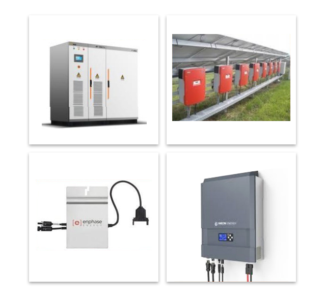
There are four options to choose from, for grid-tied inverters.
- Central inverters
- String inverters
- Microinverters
- Hybrid inverters
Central inverters
Central inverters are not commonly used anymore. They require extensive site preparations. They are used only for large-scale solar projects, such as utility-scale or multimillion-dollar projects. They are very large and are generally sized from 50 to 1000 kilowatts (kW). To give some sense of scale, a 1000 kW project would mean probably 3,000 to 4,000 solar modules.
You might also see them on some legacy systems, like 10-year-old projects.
Central inverters have fewer component connections. But they have one central point of failure since only one inverter is being used. If that breaks down, then the entire system shuts down.
String inverters
String inverters are the most common inverters now. They are attached to a set of solar modules that have been connected together in series, and can handle one to four strings.
A 10 kW solar project would mean 30–40 solar modules. This means that only one inverter is needed for the project. They are, thus, easy to maintain and troubleshoot. There are also less points of failure as compared to a central inverter.
String inverters have a warranty of 5-10 years, as compared with solar modules which have a warranty of 25 years. So the inverters may need to be replaced by Year 10 of their life. This means that those costs have to be forecasted and budgeted into the overall economics of the system, and built into the operation and maintenance planning as well.
Microinverters
Instead of one inverter which handles an entire string, these inverters are connected directly to the solar modules. They are called ‘micro’ because they are little boxes that are mounted onto the racking underneath the solar modules themselves. In this photo, the little metal boxes are the inverters which have been mounted onto the racking for the solar modules.
If you choose microinverters, you will typically need one per module, though some models can support multiple modules.
Microinverters (continued)
There are both advantages and disadvantages to installing microinverters.
There is no single point of failure because multiple microinverters operate independently, each connected to one or more modules. This also makes expansion easier, as additional modules can be added without affecting the existing setup.
Earlier we saw how the whole system could be impacted if one module is shaded. This can be avoided by installing microinverters. For example, if there are 10 microinverters and one of them shuts down, there still are nine inverters functioning. So, 90% of power still is available and the whole system will not go down.
However, you need a lot of inverters. That increases the possibility of breakdowns. If one stops working, then that one individual component will have to be located and replaced. Fixing a microinverter in the middle of the array can be challenging.
They are also approximately 30% more expensive on a per kW capacity comparison to other types. Whether to use them or not depends on various factors: How much is it going to cost to maintain the system? How are the costs being layered? Has the budgeting for the higher costs, from both the installation and operation and maintenance perspectives, been done?
Hybrid inverters
Hybrid inverters combine the functions of a battery charger and a microinverter and can operate with or without batteries. They can provide reliable power from multiple sources, including solar modules, batteries, and the utility grid.
Hybrids can store excess energy for use during blackouts. The systems also take up less space than other designs.
These inverters can convert DC from solar modules into AC to power loads, and vice versa to charge batteries.
Hybrid inverters are not commonly used.
Which of these is not an inverter?
Mapping micro-inverters/optimizers
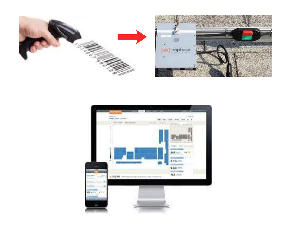
Microinverters can be mapped on a monitoring portal.
If the solar system has, for instance, 20 microinverters and one of them breaks down, trying to locate it by checking every inverter manually is not a feasible task.
Each inverter/optimizer is identifiable with its unique barcode sticker. This barcode can be scanned and mapped out on the monitoring portal. A broken or malfunctioning inverter can now be easily identified by referring to the mapped details.
Mapping each unit’s location in the portal enables individual monitoring. This makes it easy to locate specific components for repair or keep track of components for operation and maintenance, in the system.
What does a monitoring
system look like?
A solar system has 20 microinverters and one stops working. How does a monitoring portal help you find it?
Maximum Power Point Tracking
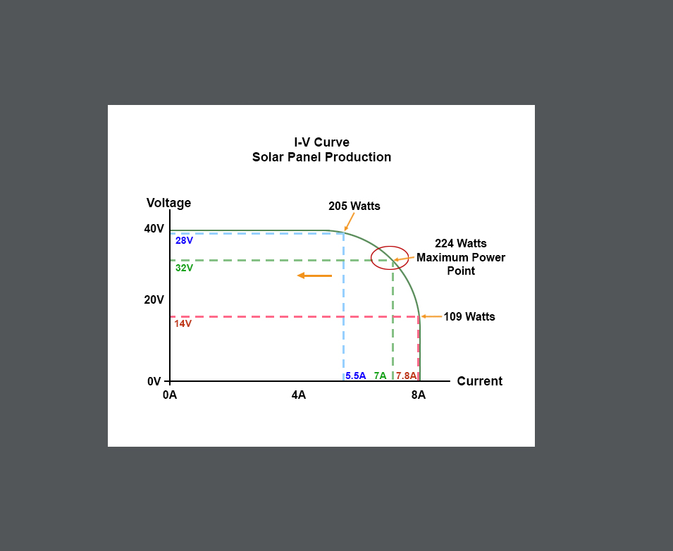
Every inverter has Maximum Power Point Tracking (or MPPT for short). The inverter changes the voltage and amperage to get maximum power.
In this graph, the red circle represents the maximum power. The vertical axis shows the voltage, and the horizontal axis shows the current in amps. In this representation, this module can produce 40 volts and 8 amps, but the optimal values are 32 volts and 7 amps. The inverter adjusts the volts and current to find the MPPT optimum spot for maximum power (that is, watts) produced.
This is the maximum power possible based on the voltage and the amperage that is being produced.
Note that the inverter is trying to produce the most power possible - not trying to maximize the voltage or the current. The inverter is able to fluctuate, to change voltage and amperage, to generate the most power possible.
Anti-islanding feature
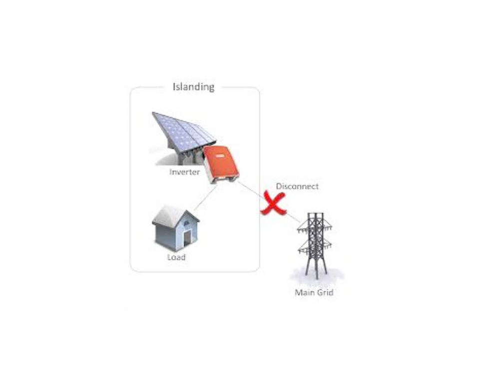
If there is a grid outage, under normal circumstances, the power would go off and nothing would be energized. However, if there is a solar power system installed on a building, that building could still technically produce power because of the solar modules and feed it back into the grid.
The anti-islanding feature is built into all grid-tied inverters to stop this from happening.
This is a critical safety mechanism.
What is anti-islanding?
What is anti-islanding?
Power optimizers
Power optimizers are similar to microinverters, except that they don't invert the power. The power remains DC. Optimizers have superior efficiency (99.5% peak efficiency) and are up to 30% cheaper than microinverters. They come with a 25-year warranty.
Note that you are adding costs when you are layering on these components. So you have to keep a balance between costs versus production versus savings versus revenue.
Power optimizers are able to calculate MPPT on a module level, for each individual module. This delivers advanced, real-time performance measurement. This makes power optimizers useful in two scenarios. Scenario 1: Solar Modules in Different Orientations
The solar modules are oriented in different directions.
One module may be facing one way, a second one another way, and a third one facing yet another way. As the sun passes over them, they will not produce the same amount of voltage and amperage because they are all facing in different directions. Installing optimizers in such a scenario would optimize the power for each individual module.
Scenario 2: Shading Impact on Solar Modules
In this scenario, a significant portion of one solar module is heavily shaded by a tree. When a solar module experiences shading, its output drops dramatically, as shaded cells can behave like resistors, restricting the flow of electricity through the entire string. While bypass diodes within the module can help mitigate partial shading by redirecting current around smaller shaded sections, they become ineffective when a module is almost entirely shaded.
If cutting the tree or relocating the system is not feasible, power optimizers offer a solution. Unlike bypass diodes that only bypass small sections of a module, an optimizer allows the rest of the solar array to function efficiently by isolating the underperforming module. This ensures that the overall system continues generating power with minimal losses despite shading.
Power optimizer system monitoring
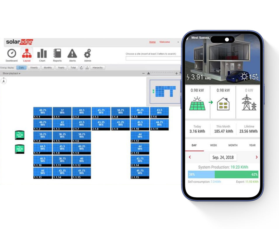
All the solar modules can be mapped into a power optimizers' monitoring system. This enables keeping checks on which modules are producing better than the other modules during the day.
The barcodes can be scanned and accessed easily from a computer, smartphone or tablet. Automatic alerts are received on system issues. If a power optimizer breaks down, it is easy to figure out where it is located and replace it.
The monitoring system presents data presentation at the module, string and system levels. It also provides visualization of photovoltaic production, the building’s power consumption as well as self-consumption.
Net metering systems—1
Net metering systems allow consumers to not only use the electricity generated by their solar modules to meet their own energy needs, but also receive compensation for any excess energy that is fed into the grid.
Consumers who have installed solar power systems use the power from that system while still connected to the grid. When the system produces more power than is required in the household/building, the excess power is sent onto the grid.
When the solar system is not producing enough power, power is taken from the grid to support the household’s/building’s needs.
Net metering is…
Net metering systems—2
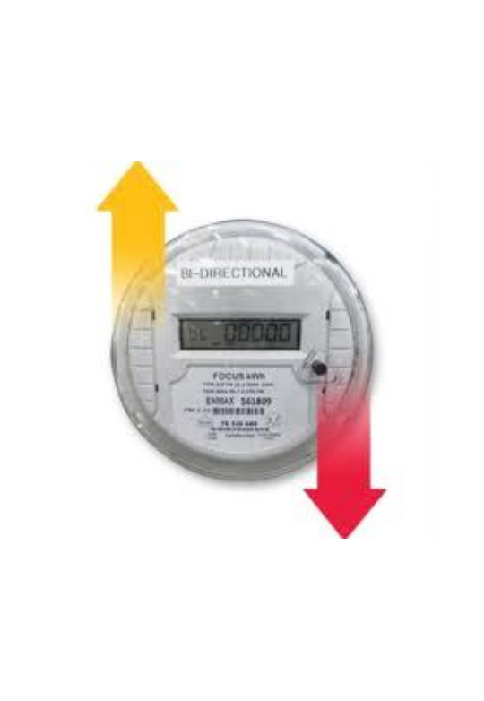
A bi-directional meter is required to keep track of the amount of power that is sent to the grid. This is because when a household/building exports to the grid, it is compensated for that excess power by getting Hydro credits back.
A bi-directional meter measures electricity flowing both to and from the grid, tracking both energy consumption and surplus solar power sent back. It records not only the electricity drawn from the grid but also the excess energy exported, ensuring accurate accounting for net metering and billing purposes.
The last step of a solar project is always for the utility to come in and replace the original meter with a bi-directional meter.
MPPT review
Does every inverter have Maximum Power Point Tracking (MPPT)? Why?
Anti-islanding review
Why is anti-islanding important when installing a solar power system?
Does net metering make financial sense?

Calculating Return on Investment, or ROI, is a way to figure out whether an investment in purchasing a solar power system makes financial sense. This is best done by determining what the payback period of the system is.
The equation is:
Total cost of solar powered system ÷ Annual electrical utility costs = Number of years to recapture the cost of system
For example, let’s say you want a solar system that costs 28,479 dollars to buy and you pay 3,754 dollars to Hydro One every year to run a building. So the calculation works out as:
$28,479 ÷ $3,754 = 7.58
This means you will start making a return on your investment after approximately seven-and-a-half or eight years. You would have made enough savings such that the project is now becoming profitable and you’re making a return on your investment. You are now not paying the utility; you are saving that money. Generally, if your payback period is 10 years or less, it is considered a good investment. If the ROI works out to be longer than 10 years, it may not be a great investment.
How do you calculate ROI (return on investment)?
Summary
This training module has provided a comprehensive overview of solar energy, focusing on the principles of solar theory. It covers the science behind solar energy conversion, including the functioning of solar modules, inverters and storage systems.
A key component is understanding seemingly mundane but essential details such as solar module warranties and specification labels. We learned about typical warranty terms, such as performance guarantees. Specification labels on solar modules provide data on power output, voltage and performance tolerance, which helps professionals assess and optimize module performance.
We saw how technology helps in improving workflows and monitoring the system efficiently.
Participants will now be equipped with the knowledge to evaluate solar modules, make informed decisions during installation, and ensure the efficiency and durability of solar energy systems for sustainable energy solutions.
Post-test
Answer these to see what landed. We’ll point you back to anything worth a second look.